Visit us at
www.Anaren.com
USA/Canada:
Toll Free:
Europe:
Asia:
(315) 432-8909
(800) 411-6596
+44 2392-232392
+86 512-62749282
odel 0 30 0100 HF
Rev A
Ultra Low Profile 0805 Balun
50 to 100 Balanced
Description
The B0430J50100AHF is a low cost, low profile sub-miniature unbalanced to
balanced transformer designed specifically for differential inputs and output
locations on next generation A to D and D to A Converter ICs in an easy to use
surface mount package, covering 400 MHz3000 MHz. The B0430J50100AHF is
ideal for high volume manufacturing and delivers higher performance than traditional
wire wound baluns. The B0430J50100AHF has an unbalanced port impedance of
50& and a 100& balanced port impedance. This transformation enables single
ended signals to be applied to differential ports. The output ports have equal
amplitude (-3dB) with 180 degree phase differential. The B0430J50100AHF is
available on tape and reel for pick and place high volume manufacturing.
Note that for optimal performance, the B0430J50100AHF should be used with a 10
pF series capacitor on the unbalanced port as shown in p. 2 & 3.
Detailed Electrical Specifications:
Specifications subject to change without notice.
ROOM (25?/SPAN>
??/DIV>
?SPAN class="pst B0430J50100AHF_2592117_11">C)
Parameter
Min.
Typ.
Max
Unit
Frequency
400
3000
MHz
Unbalanced Port Impedance
50
Balanced Port Impedance
100
Return Loss
8.4
9.9
dB
Insertion Loss*
3.4
4.0
dB
Amplitude Balance
0.7
1.4
dB
Phase Balance
7
12
Degrees
CMRR
25
dB
Power Handling
1
Watts
Features:
" 400 3000 MHz
" 0.7mm Height Profile
" 50 Ohm to 2 x 50 Ohm
" Low Insertion Loss
" Designed for A-D and D-A
Converters
" Surface Mountable
" Tape & Reel
" Non-conductive Surface
" RoHS Compliant
" Halogen Free
Operating Temperature
-55
+85
篊
* Insertion Loss stated at room temperature (Insertion Loss is approximately 0.1 dB higher at +85 篊)
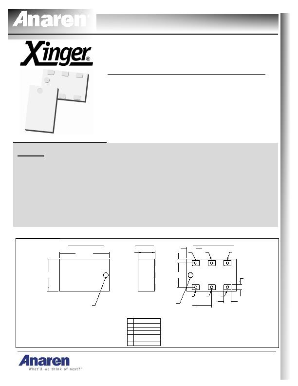
Outline Drawing
2.04?.10
1.29?.10
0.70?.05
1
2
3
6
5
6x
0.30
6x
0.22
4x 0.65
6x 0.98
Orientation Marker
Denotes Pin Location
4
Orientation Marker
Denotes Pin Location
TOP VIEW (Near Side)
SIDE VIEW
BOTTOM VIEW (Far Side)
5
4
2
1
6
3
Pin
Unbalanced Port
NC
Balanced Port
Mechanical Outline
-Dimensions are in Millimeters
GND
Designation
2x 0.15
4x 0.37
GND
Balanced Port
-Tolerences are Non-Cumulative
发布紧急采购,3分钟左右您将得到回复。
相关PDF资料
B0809J50ATI
XFRMR BALUN RF 850-915MHZ 0805
B0922J7575A50HF
XFRMR BALUN RF 950-2150MHZ 0805
B0922N7575AHF
XFRMR BALUN RF 950-2150MHZ 0404
BD0205F5050AHF
XFRMR BALUN RF 70-1000MHZ 1608
BD0810J50100AHF
XFRMR BALUN RF 800-1000MHZ 0805
BD0810J50200AHF
XFRMR BALUN RF 800-2000MHZ 0805
BD0826J50200AHF
XFRMR BALUN RF 800-2600MHZ 0805
BD1631J50100AHF
XFRMR BALUN RF 1.6-3.1GHZ 0805
相关代理商/技术参数
B-043-24-N
功能描述:CABLE TERMINATION RG/U 178,404 制造商:te connectivity raychem cable protection 系列:* 零件状态:过期 标准包装:100
B-043-26-N
功能描述:焊料和屏蔽管 HS-COAX TRMNTR RoHS:否 制造商:TE Connectivity / Raychem 类型:Shield Terminators 材料:Polyvinylidene Fluoride 内径:5.08 mm 长度:16.5 mm 最低收缩温度: 系列:S03
B-043-28-N
功能描述:焊料和屏蔽管 B-043-28-N RoHS:否 制造商:TE Connectivity / Raychem 类型:Shield Terminators 材料:Polyvinylidene Fluoride 内径:5.08 mm 长度:16.5 mm 最低收缩温度: 系列:S03
B-043-30-N
功能描述:焊料和屏蔽管 B-043-30-N RoHS:否 制造商:TE Connectivity / Raychem 类型:Shield Terminators 材料:Polyvinylidene Fluoride 内径:5.08 mm 长度:16.5 mm 最低收缩温度: 系列:S03
B0434-
制造商:Coilcraft Inc 功能描述:Power inductor, planar, for TI UCC3580, 10% tol, SMT, RoHS
B04348A
制造商:Thomas & Betts 功能描述:FLAP, GRAY PAINT
B0434-AL
制造商:Coilcraft Inc 功能描述:Power inductor, planar, for TI UCC3580, 10% tol, SMT, RoHS
B0434-ALB
制造商:Coilcraft Inc 功能描述:Power inductor, planar, for TI UCC3580, 10% tol, SMT, RoHS